Structural Project using: Autocad, Etabs, Safe, S-concrete and Excel Softwares
INTRODUCTION
Any structure in the world begins
with an architectural plan of the elevation, plans and 3D views drawn by an
architect, followed by structural calculations and checks and design by a
structural or civil engineer.
In this project, we will see the
general steps used by a civil engineer to design a reinforced concrete residential
building in Lebanon, using Autocad, Etabs, Safe, S-concrete and Excel Softwares.
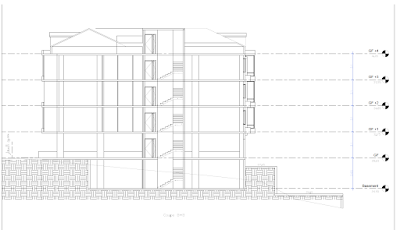
Figure 1: Elevation
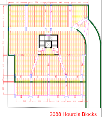
Figure 2: Basement Plan
It begins with architectural elevation
(Fig. 1) and plans of the building (Figures 2 and 3), that the architectural engineer
has drawn, by making assumptions for the column sections and places, as well as
the shear walls distribution and thicknesses.
Your role as a structural or a civil engineer is to check if the column sections are good to retain the building, and if the shear walls are well distributed. You also have to find the reinforcement in all the structural elements: columns, shear walls, retaining walls, beams, slabs, stairs and foundation.
In the “Figure 4”, we have:
· 3 pink shear walls
· Blue doors
· Light blue windows
· Yellow stairs
· Wight curtain walls
· Green dimensions
· Red opening
ETABS SOFTWARE
First of all, delete all the non-structural elements (windows, doors…) and draw the model on “ETABS Software” as you can see in “Figure 5”.
The next step is to define and
add all the loads (except the self-weight as it will be calculated by the
software):
· Live load
·
Super imposed Dead Load (including
the hourdis blocks loads)
·
Wind load
·
Seismic load (in x and y
direction, positive and negative, with and without drift)
·
Soil pressure load
EXCEL SHEET
Before defining the loads
combinations, open the “Excel Sheet” to begin the analysis check of your
model, to see if it is stable or not and to see if you have to use the dynamic
analysis or not “Figure 6”.
Check the center of mass and
rigidity, the diaphragm classification, the story drift in X and Y, the wind displacement,
the accidental torsion in X and Y, the mass and stiffness irregularity, P-delta
effect and finally the scaling of dynamic.
In our case, we used the dynamic analysis, and the semi-rigid diaphragm as a conclusion from the excel analysis check.
You can now continue the ETABS
calculations, and perform the design of the structural elements.
After structural calculation, some
of the columns drawn by the architect were modified as the 2 columns in the middle
top of the figure 4, and the section of other columns have been changed based
on “ETABS” columns design results. But make sure not to modify the place of the
columns to not change the architectural distribution of the rooms.
The column that is in the middle bottom of the shear walls in the “Figure 4” was also replaced with a horizontal long shear wall, because the shear wall design using “ETABS” software was not acceptable before this modification (Figure 7).
SAFE SOFTWARE
The next step is to export each floor alone to “SAFE” software to check the log term and short term deflection for the slabs and beams, and to find the needed reinforcement for the slabs (Figure 8) and footings. The slab thickness taken in this project was 25 cm, and it was a hourdis slab type for all the floors.
Draw the ribbed slab on AutoCAD
and distribute the hourdis between the ribs (Figure 9).
Figure 9: Basement hourdis slab
S-CONCRETE SOFTWARE
After designing the structural
elements, export the loads of the beams, columns and shear walls to “S-concrete”
software and find the reinforcement distribution of these elements (Figure 10) based on ACI
318-11 code.
Figure 10: Column reinforcement using "S-concrete" software
You can then export the reinforcement to AutoCAD, and modify them.
You can also skip the S-concrete step, if you know well the code requirements and you can draw correctly the reinforcements by yourself.
AUTOCAD SOFTWARE
Now, draw all the columns
sections (Figure 11) and make a table on AutoCAD that summarize the columns
results for each story (Figure 12).
Figure 11: Columns reinforcement in Basement floor
For each floor, draw using AutoCAD (Figure 13):
·
A plan of the columns and
their axis
·
A drawing and a table for
the column reinforcements
·
A plan of the slab reinforcement
·
A plan of the beams
·
A plan of the shear walls
·
A drawing and a table for
the beams reinforcements
Draw also:
·
A plan showing the stairs reinforcement
·
The retaining walls
reinforcements in plan and elevation
·
A plan for footing dimensions
and another one for footing reinforcements
In this project, raft footing of
60 cm thickness is used because we have a basement floor.
An ETABS, Safe or S-Concrete file
can be easily exported to AutoCAD and modified there.
You can also draw the model on
Revit Software to perform a 3D view for all the elements!


Wow, amazing block structure! How long
ReplyDeleteHave you written a blog before? Working on a blog seems easy.
The overview of your website is pretty good, not to mention what it does.
In the content!
etabs-crack-download
Thank you!
DeleteYes I have written 3 blogs before this one, and many others after it.
To write a blog you should first of all have an interesting topic to talk about, then to arrange the ideas in a simple way so anyone could understand.
O KMSPico Ativador é a escolha ideal para quem precisa ativar produtos da Microsoft de maneira rápida e sem complicações. Com esse software, todas as funcionalidades do Windows e do Office podem ser liberadas facilmente. Simples de usar, eficiente e seguro, é a solução mais confiável para garantir que seus programas estejam sempre atualizados e operando corretamente. https://nortadownload.com/kmspico/
ReplyDelete