SOIL LAB REPORT: The liquid limit test.
SOIL LAB REPORT
The liquid limit test
Abstract: This blog post is a report of laboratory soil analysis to find the liquid limit which is a coefficient needed for soil classification.

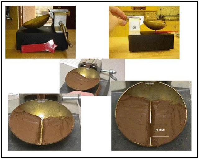
Apparatus: We use a brass cup and a hard rubber base,
spatula, wet soil, balance, oven.

This device consists of a brass cup and a hard rubber base.
The brass cup can be dropped onto the base by a cam operated by a crank.

Objective: Determine the liquid limit.
Procedures:
1. To perform the liquid limit test, one must
place a soil paste in the cup.
2. A groove is then cut at the center of
the soil pat with the standard grooving tool.
3. By
the use of the crank-operated cam, the cup is lifted and dropped from a height
of 10 mm (0.394 in.).
4. The moisture content, in percent,
required to close a distance of 12.7 mm (0.5 in.) along the bottom of the
groove.

6. The moisture content of the soil, in
percent, and the corresponding number of blows are plotted on semi-logarithmic
graph paper
7. Place
a portion of the previously mixed soil into the cup of the liquid limit
apparatus at the point where the cup rests on the base. Squeeze the soil down
to eliminate air pockets and spread it into the cup to a depth of about 10 mm
at its deepest point. The soil pat should form an approximately horizontal
surface
8. Place
a portion of the previously mixed soil into the cup of the liquid limit
apparatus at the point where the cup rests on the base.
9. Squeeze the soil down to eliminate air pockets and spread it into the cup to a depth of about 10 mm at its deepest point. The soil pat should form an approximately horizontal surface.
10. Use
the grooving tool carefully cut a clean straight groove down the center of the
cup. The tool should remain perpendicular to the surface of the cup as a groove
is being made.
11. Turn the crank of the apparatus at a rate of approximately two drops per second and count the number of drops, N, it takes to make the two halves of the soil pat come into contact at the bottom of the groove along with a distance of 13 mm (1/2 in.)
12. Place
the soil into a moisture can. Immediately weigh the moisture can containing the
soil
13. Place the can into the oven for at least 16 hours.
14. Determine the mass of dry soil.
15. Repeat steps for at least two additional trials producing successively lower numbers of drops to close the groove. One of the trials shall be for a closure requiring 25 to 35 drops. Determine the water content from each trial by using the same method.
Discussion:
The relationship between moisture content and log N is approximated as a straight line. This line is referred to as the flow curve.
The moisture content corresponding to N = 25, determined from the flow curve, gives the liquid limit of the soil.
The slope of the flow line is defined as the flow index and may be written as:

|
Number
of cans |
Mass
of can without soil |
Mass
of can + wet soil |
Number
of blows (N) |
Mass
of can + dry soil |
Mass
of wet soil |
Mass
of dry soil |
|
1 |
4.21
g |
27.08
g |
14 |
20.52
g |
22.87
g |
16.31
g |
|
2 |
4.23
g |
35.5
g |
29 |
26.19
g |
31.27
g |
21.96
g |
|
3 |
4.16
g |
22.28
g |
38 |
16.95
g |
18.12
g |
12.79
g |

Calculation
of water content: w = (Mw) / (Ms)
Mass
of water = mass of wet soil – mass of dry soil
W1
= (22.87 – 16.31) *100 / 16.31 = 40 %
W2
= (31.27 – 21.96) * 100 / 21.96 = 42.39 %
W3
= (18.12 – 12.79) *100 / 12.79 = 41.673 %
From
the graph, for N = 25, w = LL = 41.75%
References:
1) Soil
lab (BAU).
2) Book: principles of geotechnical engineering (25th edition).
Comments
Post a Comment